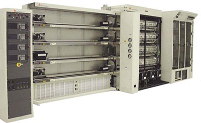
BRUCE DIFFUSION FURNACE – BDF 41
Horizontal diffusion furnace for 200mm wafers and smaller
- The Model BDF-41 four stack diffusion furnace system is designed to accept process wafers up to and including 200mm in diameter.
- The standard BTI convention for a right handed furnace is when viewing the furnace from the operator’s side, the load station is to the right and the source cabinet is to the left. Tube level one (1) is the uppermost tube and tube level four (4) is the lowest.
- BTI Standard Colors are standard light gray and charcoal gray. Refurbished equipment color will be as received.
- Installation, operation and maintenance instructions on clean room paper are provided upon shipment.
Detailed System Features
System Controls
The BDF-41 System Control is a distributed control system which uses the 7360 DDC Microcontroller as a host and individual microcontroller modules for dedicated control tasks. All modules are managed by a system controller microprocessor. Most of the control electronics are housed in a self standing control cabinet located at the end of the load station or adjacent to offset shroud. Satellite modules are located elsewhere in the Furnace system.
Control Cabinet
- Location: Flexible,
- Components: 7355X & 7360 DDC, Communication I/O, Boat Loader Controller and Alarm Panel
- WAGO I/O replaces our (2) Quad I/o modules per tube level.
- Each module has sixteen (16) channels (input and output); Expandable by adding additional modules.
- Independently powered by an unregulated 24 VDC power supply rated at 20A.
- Provides visual and audible indication of system and tube level alarms with manual reset. An alarm silence switch is also provided.
- Integrated with system controller for alarm activated recipe instructions. System Alarms includes:
- Load Station Blower Operation
- Scavenger Exhaust
- Mainframe Stack Overtemp
- Mainframe Fan Fail
- Gas Cabinet and Tube Foyer Exhaust
- Instrument Power
- Power Failure
- Tube level alarms are tied to indicator lights at each tube level to expedite diagnostics.
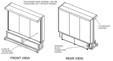
Flowhood
- Class 10 ULPA Filter System (0.125 micron, 99.9995% efficiency). Removable from rear.
- Laminar Flow region covers full length of load station.
- All surfaces exposed to wafers are constructed of mirror-finished stainless steel.
- Readily replaceable front mounted pre-filters.
- Blowers mounted in base, with operation verified through System Alarm circuit.
- Overhead fluorescent lighting, enclosed with tempered glass.
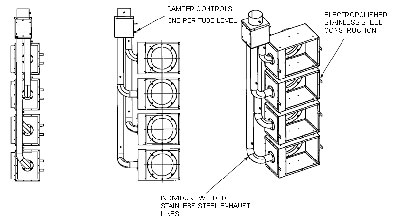
Scavenger & Exhaust System
- Individual tube level boxes with independent exhaust controls.
- All welded construction utilizing heavy gauge electro-polished stainless steel.
- Configurable to all Atmospheric and VCVD applications.
- 3.0″ diameter (76 mm) exhaust lines fabricated from corrosion resistant stainless steel components for each tube level.
- Individual tube level exhaust control, and monitoring via separate photohelic gauges.
- Exhaust control located at the top of the scavenger assemblies.
- One exhaust assembly terminating in a 6″ (152mm) diameter collector box.
- Exhaust monitored and tied into system alarms.
- Photohelic gauge at each tube level (Dwyer Model #3000 O AV) to measure static pressure (0-.5″H2O, 0-13mm H2O).
- Gauges mounted at tube levels on the load island side of the offset shroud.
- Adjustable gauge setpoints for high and low flows are tied into tube level DDC Alarms.
- Includes stainless steel and Teflon interconnect plumbing from gauges to 3.0″ exhaust lines. Gauge plumbing is accessible through a removable panel on the rear shroud.
- NOTE: The electronics assembly for the photohelic gauge is mounted inside the shroud assembly.
Main Frame Section
- Furnace section will accept a maximum of four, 5 zone heating elements configured for 125 mm, 150 mm or 200mm wafer processing.
Heating Elements
- Each heating element is provided with one SCR/XFMR power controller with an individual trigger board for each zone. Air cooled zero crossover fired SCR’s are located in the secondary of the transformer.
- Ten (10) thermocouples per heating element, Type “S” (platinum vs. platinum 10% rhodium). Two (2) thermocouples per zone, one for control and one for overtemperature. One additional undertemperature spike thermocouple is supplied on pyrogenic oxidation tube levels.
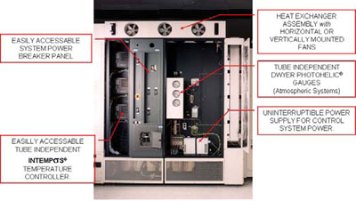
- The INTEMPσS™ Intelligent Temperature / Overtemperature control module mounted on the rear of the furnace module.
- An independent stack overtemperature protection system to monitor furnace cabinet temperature: AUDIBLE ALARM AT 230°F and SYSTEM SHUT-DOWN AT 265°F
- Deposition line (transition) conduits are supplied at all tube levels and terminate in exhausted areas (scavenger and tube foyer), when gas lines are installed.
- Bi-fold front doors are lockable by keys.
- Profile thermocouple receptacles are supplied on the source end panel at each tube level and are accessible from the tube foyer.
- Quartz lined profile thermocouple storage tubes are provided at each tube level.
Electrical Package (50 Hertz)
- Single power input of 480Vac 60Hz or 380V 3 Phase 50 Hz rated at 350A
- A 10 KVA step-down transformer supplies single phase 220/120V to the furnace system. (Located in the scavenger section).
- Provisions for connection to customer supplied UPS system will supply filtered and regulated power to the DDC Microprocessor modules.
- Failsafe EPO circuit will interrupt all system power (including UPS) and does not require power to function. Two (2) recessed switches are included with the furnace.
- Main circuit breaker is rated at 350 A.
- Tube level circuit breaker is rated at 125 A.
- Independent tube level breaker protection for 24V and 15V power supplies and UPS power to microcontrollers.
- Additional accessories are protected by breakers in the load center.
- All electrically energized components with potentials greater than 45V, are either individually shielded or inherently designed to prevent inadvertent contact.
- All conductive doors, panels, frames and chassis where a hazardous potential is present >45V are individually grounded.
- Control cable breakpoints with bulkhead style connectors are provided in the gas cabinet, scavenger, load station and control cabinet for ease of assembly and maintenance. Power breakpoints are also provided at these locations by means of terminal blocks.
Heat Exchanger
- Water cooled with finned copper cooling coils.
- 2400 CFM (68.0 cubic meters minute) exhaust through three 8.0″ (203mm) fans, top exhaust
- Fan operation monitored and tied into system alarms.
Source Cabinet
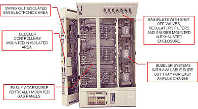
Gas Cabinet
- Gas panels per are mounted vertically to enhance accessibility of gas system components for replacement or maintenance.
- Gas panels are accessed through polycarbonite doors.
- Vertical exhaust through the full height of the cabinet maintains flow across all gas system components.
- Cabinet Exhaust is monitored and tied to a system alarm.
- Gas electronics are vertically mounted at each tube level at the end of the cabinet.
- Additional process electronics and power supplies are located in the cabinet base.
- A dual accessory power receptacle is provided at each tube level with individual 15 amp breakers mounted in the base.
- The gas connections made at the top of the cabinet are within the exhausted area and are sealed with foam lined sealing plates for ease of access.
- Illumination is provided by fluorescent lighting
Tube Foyer
- Foyer is independently exhausted; Cabinet exhaust is monitored and tied to a system alarm.
- Access is provided via tube level polycarbonite doors.
- Stainless steel tube level shelves are perforated to maintain airflow and to provide mounting for torches, and process accessories.
- Illumination is provided by fluorescent lighting.
- Maintenance cart connection and tube selector key-switch is mounted in the cabinet base for remote system control.
Gas Inlet & Manifolds
- Inlet assemblies consist of a shutoff valve, regulator, gauge, filter and manifold drop to the four tube levels.
- Assemblies are housed in a 10″ (254mm) canopy at the top of the gas cabinet with active components mounted in a front angled panel for ease of access and viewing.
- All connections are made in the exhausted cabinet area.
- Inlet assemblies are constructed of 316L grade tubing, Micro-T weld fittings and VCR™ fittings. All components are electropolished.
- Assemblies are configured with no tubing bends (fittings or 10 X tubing diameter arcs only).
- Systems leak integrity tested to 10-8 cc/sec He.
- Low N2 pressure circuit is included in the nitrogen inlet assembly and interlocked with safety shutoff valves and auto purge functions.
- Air manifold (1) is supplied to service air operated valves in the gas control system and includes a shutoff valve.
- Maximum of 11 gas inlets plus 1 air manifold